Online oil monitoring system
On important machines the oil is monitored continuously. A sensor on the oil line measures, the monitoring screen shows the status in colours and raises an alarm when a limit is crossed. All readings are logged as trends.
- 1Vibration · Input shaft bearing
- 2Temperature · Input shaft bearing
- 3Vibration · Output shaft bearing
- 4Temperature · Output shaft bearing
- 5Oil sensor · Oil circulation line
What it monitors
- Viscosity, density and dielectric (oil ageing)
- Water in oil (ppm and water activity)
- Particle contamination (ISO 4406 code)
- Wear-metal particle trend
- Oil temperature, and vibration if required
How it works
The sensor measures, the monitoring screen displays and logs the readings. Alarm limits are set during installation from the machine's normal operation. The system can be connected to a local server or to online monitoring.
Monitoring screen
Each measurement appears on its own card on the monitoring screen. When a value nears its limit the card turns yellow, and when it crosses the limit the card turns red. The trend screen shows recent days and the limit lines.
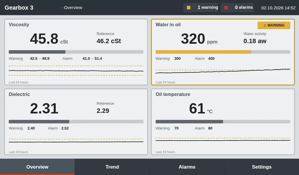
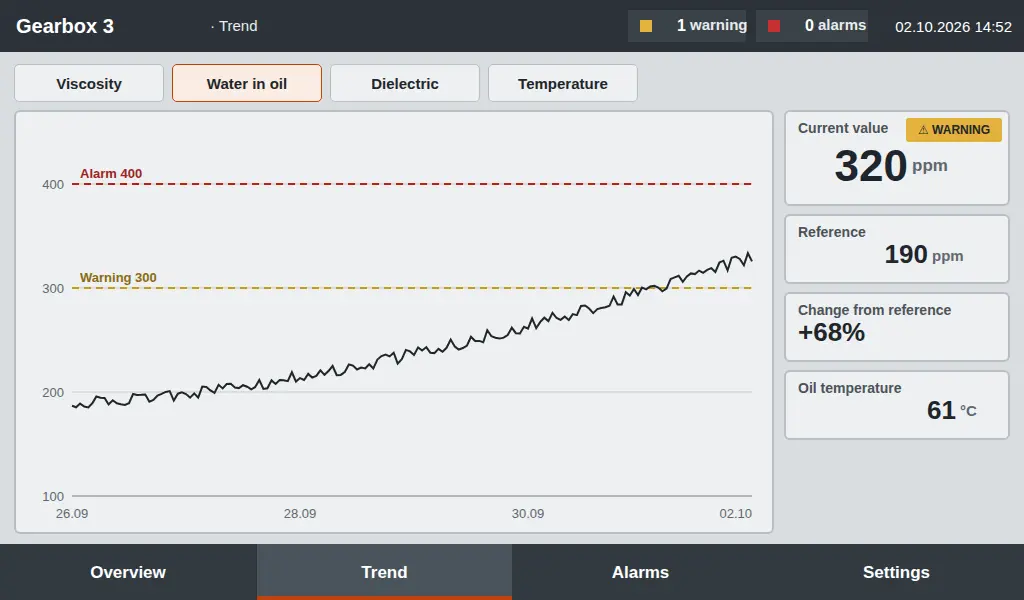
The screens are sample designs and the values are illustrative. In a real installation the layout and content may differ depending on the machine and the sensors used.
Sensor location
On a gearbox the sensor is fitted to the oil sump or the circulation line. In a hydraulic system it is fitted to the return or bypass line. Its maximum working pressure is 15 bar, so it is not used on the high-pressure line.
- 1Vibration · Pump bearing
- 2Temperature · Pump bearing
- 3Oil sensor · Return line
- 4Particle sensor · Return line
How the sensor connects to the oil line
The sensor screws into a threaded port on the oil line. A sealing ring is used at the connection. The measuring probe sits in the flowing oil, while the sensor body stays outside the line. The right connection point is chosen during the site survey.
- 1Connector · The sensor cable connects here
- 2Sensor body · Stays outside the oil line
- 3Sealing ring · Prevents oil leaks at the connection
- 4Oil line · The sensor screws into the pipe or sump wall
- 5Measuring probe · Sits in the flowing oil and takes the measurement
- 6Oil flow · The probe measures the oil passing through the line
Specifications
Sensor selection considers the measuring ranges, the working pressure and the connection size together.
| Parameter | Multi-parameter oil sensor | Moisture-in-oil sensor | Online particle counter |
|---|---|---|---|
| Viscosity | 1–1000 cSt (±5%) | — | — |
| Density | 600–1250 kg/m³ (±3%) | — | — |
| Dielectric constant | 1–6 (±3%) | — | — |
| Water activity | 0–1 aw | 0–1 aw (±0.03) | — |
| Dissolved water | 0–5000 ppm (±10%) | 0–5000 ppm | — |
| Particle counting | — | — | 1–100 µm range, ISO 4406 code |
| Oil temperature | −40…+120 °C | Measured | On data sheet |
| Max. pressure | 15 bar | On data sheet | On data sheet |
| Supply | 24 V DC | 24 V DC | On data sheet |
| Housing and protection | 316 stainless steel, IP66 | IP66 | On data sheet |
| Connection | M39×1.5 | G3/4 | On data sheet |
Values are from the sensor data sheets. Results in the plant may differ. The full data sheet is available on request.
Request a quote for the data sheet and pricing.